In the following steps, you will learn how to create and configure a new Multiwell workspace. We will walk through inserting and setting up a basemap, importing borehole coordinates, and visualizing your data via a section view. You will also learn how to link markers, add new markers, assign lithology, and flatten your cross-section for more efficient analysis.
By the end of this tutorial, you will have a clear understanding of how to set up a WellCAD project and effectively manage your borehole data. Let’s get started!
Creating a New Document
- Open WellCAD, go to File > New or select New Field Document from the start page.
Adding a Basemap
- Insert a basemap file (with defined coordinates).
- Enter Top (North), Bottom, Left (West), and Right coordinates to position the map.
- Use zoom tools to fit the map on-screen.
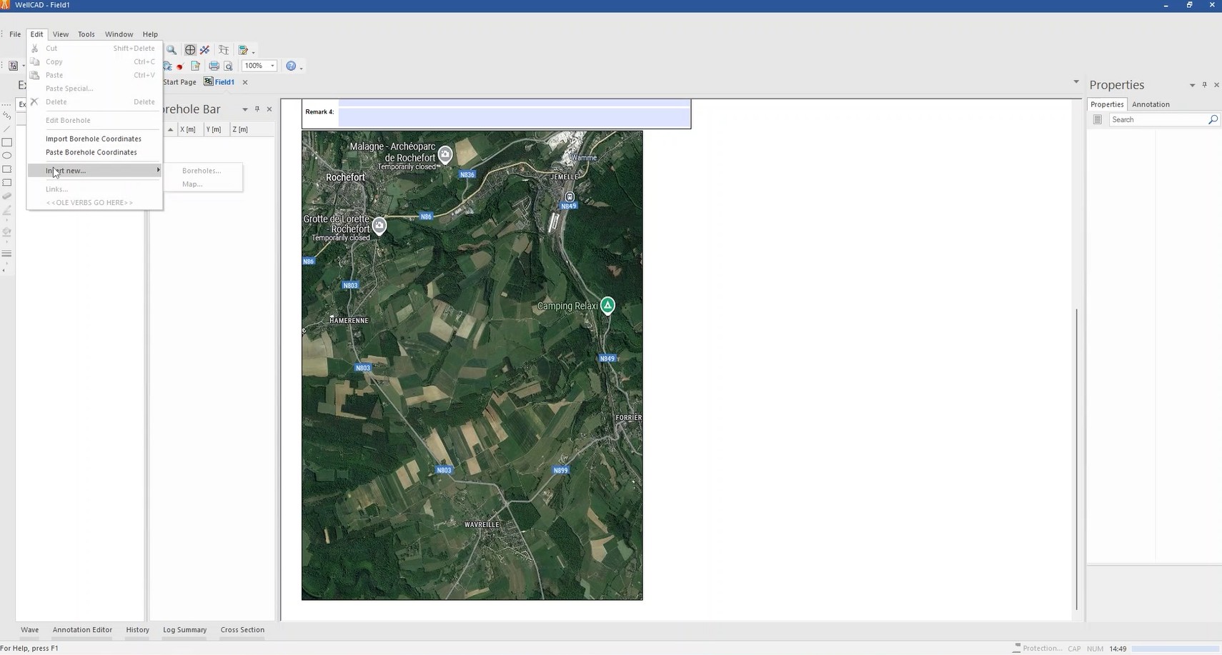
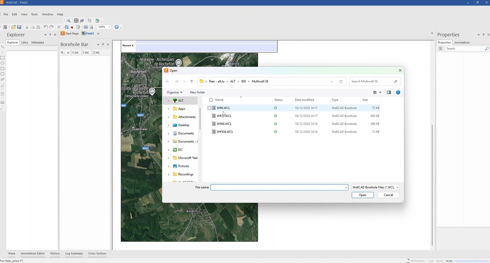
Inserting Boreholes
- Select Edit > Insert New Boreholes and choose multiple files with Shift+Ctrl.
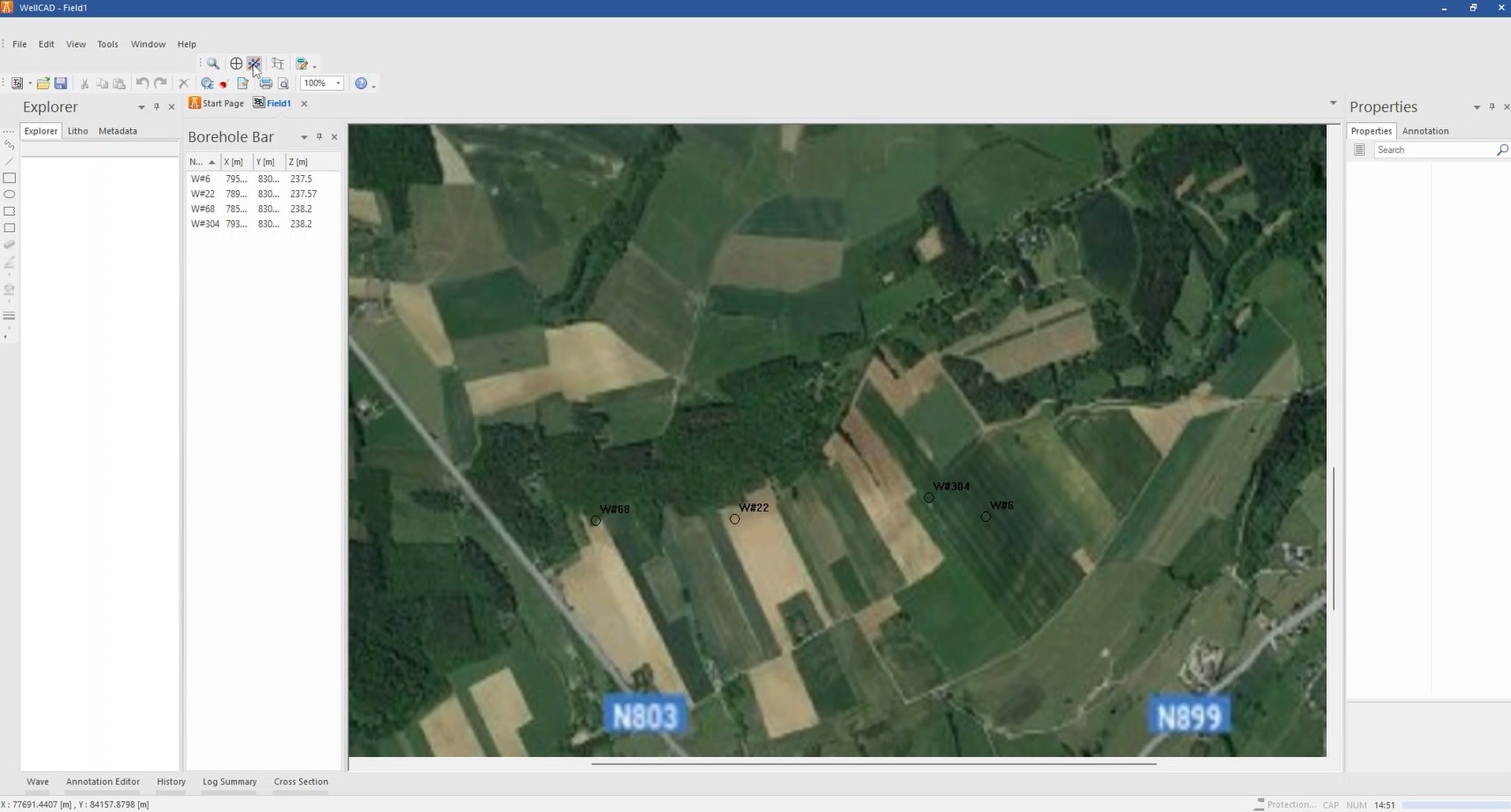
- Initially, coordinates are all set to zero.
- Use Edit > Import Borehole Coordinates to load the correct X, Y, and Z from an ASCII file
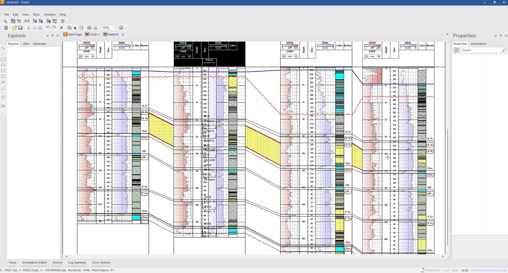
Creating a Section Line
- Activate Section Mode.
- Shift+click in sequence across boreholes to create a section line; release Shift and click again to confirm.
- Switch to Section View to see the boreholes along that line.
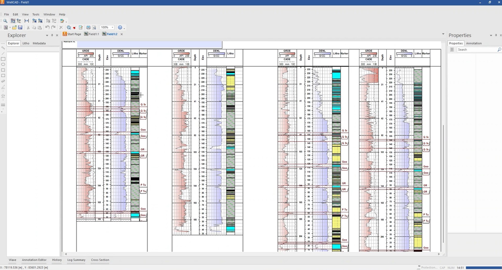
Markers and Surfaces
- Brown lines in boreholes represent markers/surfaces.
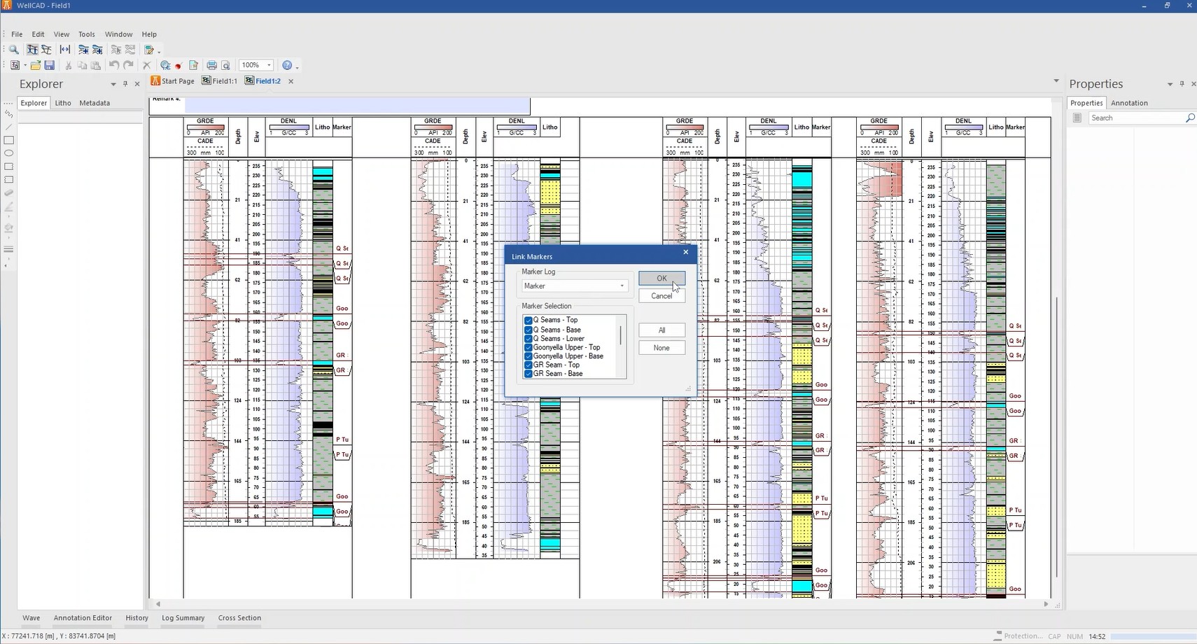
- Use Edit > Link Markers to link identical markers across boreholes.
- Edit > Add Markers from Surfaces to add missing markers.
- Insert Surface to add a new marker; name it, choose style, then Shift+drag it across boreholes.
Assigning Lithology
- Double-click between markers to assign a lithology pattern.
Flattening the Section
- View > Flatten Surface flattens the section based on a selected marker; View > Unflatten Surface reverts it.